
|
|
|
|
3D Graphics (1 / 2)
A collection of my 3D graphics experiments. Some older projects on the second page.
Many of my Haskell and Rust
projects are also graphics related.
|
Old - Some content is 10+ years old, not representing my current thoughts
|
Index
|
 |
|
3d Graphics (1 / 2) ▷ |
|
|
|
3d Graphics (2 / 2) ▷ |
|
|
|
Work ▷ |
|
|
|
Machine Learning ▷ |
|
|
|
|
Haskell ▷ |
|
|
|
Rust ▷ |
|
|
|
Physics ▷ |
|
|
|
Compression ▷ |
|
|
|
Web & Networking ▷ |
|
|
|
Meshing ▷ |
|
|
|
Miscellaneous ▷ |
|
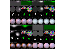
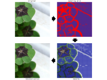
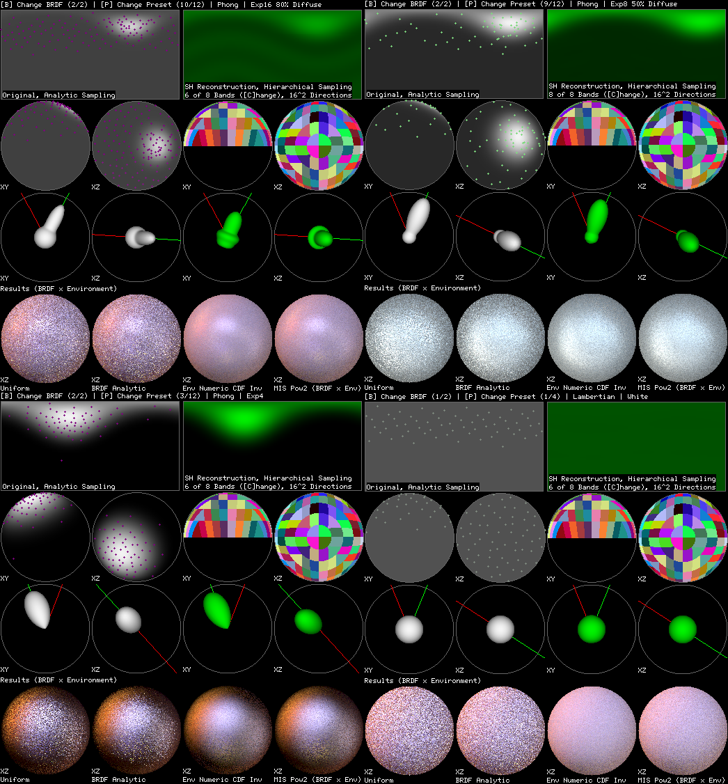
Product Importance Sampling
A framework for experimenting with product importance sampling, HDR environment maps, QMC and various BRDF models.
This was originally started to investigate the excellent
Importance Sampling Spherical Harmonics paper and compare it to some other product sampling approaches.
|
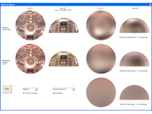
Comparison between analytic BRDF sampling, environment CDF inversion, Multiple Importance Sampling (see Veach's Thesis) and
product sampling using hierarchical sample warping on an SH representation of the BRDF. There are more promising solutions for product sampling (see Claberg,
Jarosz and Ramamoorthi). Debug displays showing the SH basis and the Shirley97 disk-to-square mapping can still be seen.
|
|
|
|
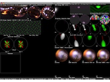
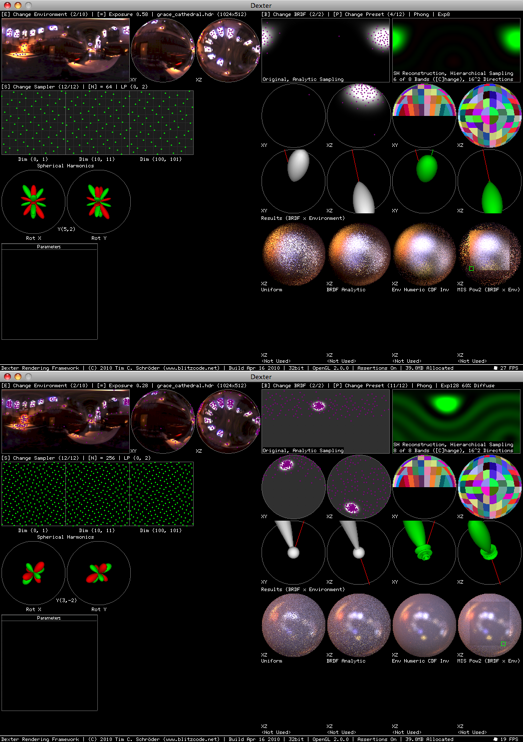
It's an OpenGL application running on OS X with GLFW. There's a framework
for plotting spherical functions, samples and images in various projections and it all updates nicely in realtime.
AntTweakBar is used for some parameter editing.
|
|
|
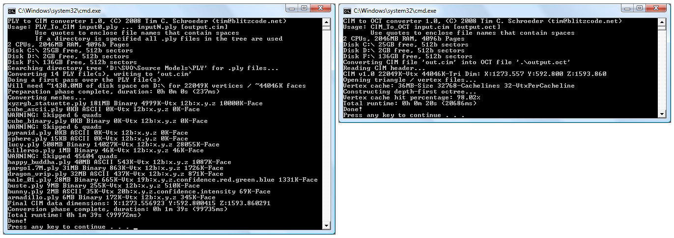
Sparse Voxel Octrees
Some early experiments with Sparse Voxel Octrees (SVOs), out-of-core mesh processing
( Isenburg and Lindstrom
have some fantastic papers on this), efficient disk I/O and caching, streaming of
PLY files and designing better disk representations
for large meshes. This was mostly inspired by Jon Olick's
SIGGRAPH talk.
I also have some ideas about dumping out shading grids from a REYES renderer and converting them to a voxel representation.
|
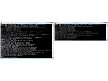
This is still work-in-progress, mostly the pre-processing tools have been
written.
|
|
|
Radiosity
This is a radiosity system I implemented. It consists of three programs: A meshing application using
various D3DX functions from the August 2005 DirectX SDK, a radiosity solver based on code from my
physically based rendering experiment and a
viewer using OpenGL / GLSL. All light transport is computed with spectra
instead of normal RGB colors. Measured geometry and emission / reflectance spectra from the
Cornell box have been used. The result of the
simulation is stored per-vertex and can be displayed in realtime. The PRT mesh refinement functions of
D3DX turned out to be not very suitable to generate a good mesh for the radiosity solver. Meshing functions
which can optimize for one set of known light sources would give likely better results. The book
Radiosity and Global Illumination is an excellent introduction to the radiosity method.
|
|
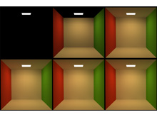
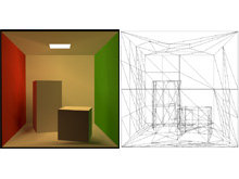
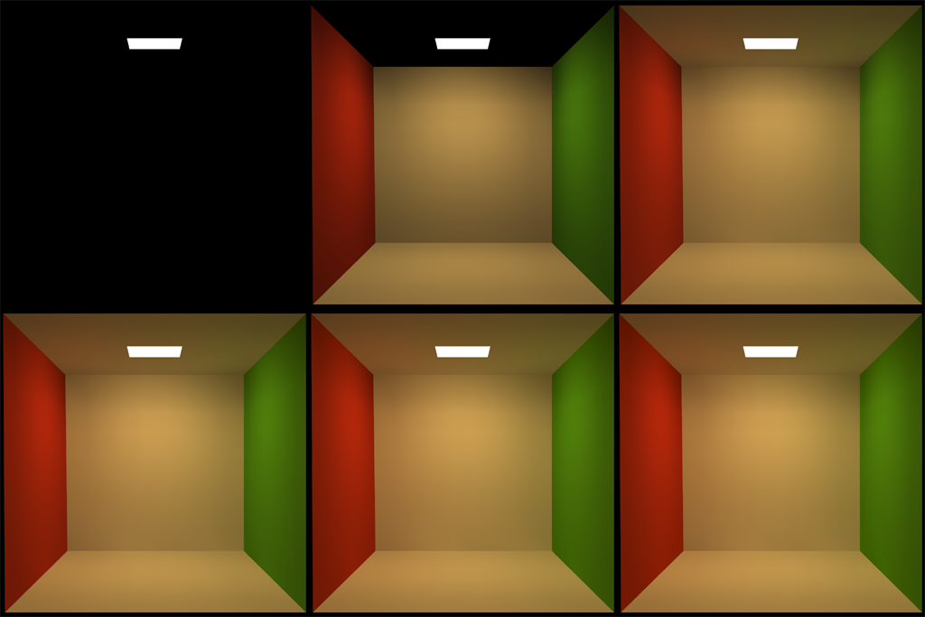
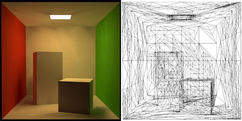
First six iterations of the radiosity solver for a simplified Cornell box. Computation time is a
few seconds on a 3Ghz P4. Subtle color bleeding effects can be seen on ceiling and floor. Normalization
has been used for tone mapping. High exposure causes the light source to go white.
|
|
|
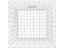
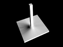
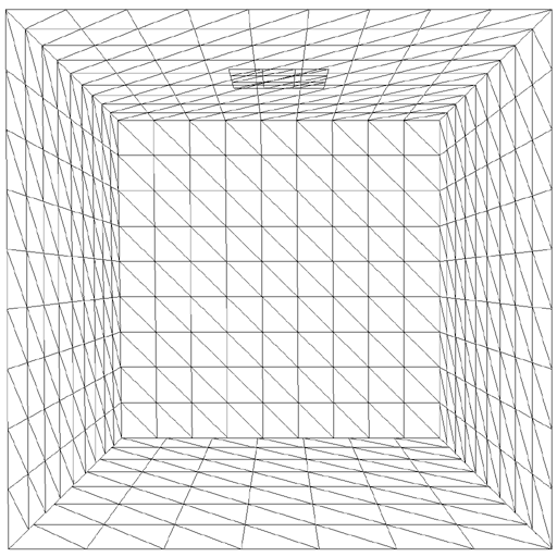
The radiosity mesh used in the pictures above. Since the scene contains no shadow discontinuities
a simple uniform tessellation using D3DXTessellateRectPatch() provides acceptable results. The
subtle darkening supposed to appear along the edges of the box can't be captured by the coarse mesh.
|
|
|
|
|
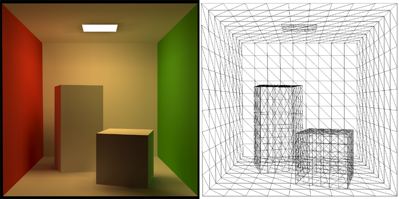
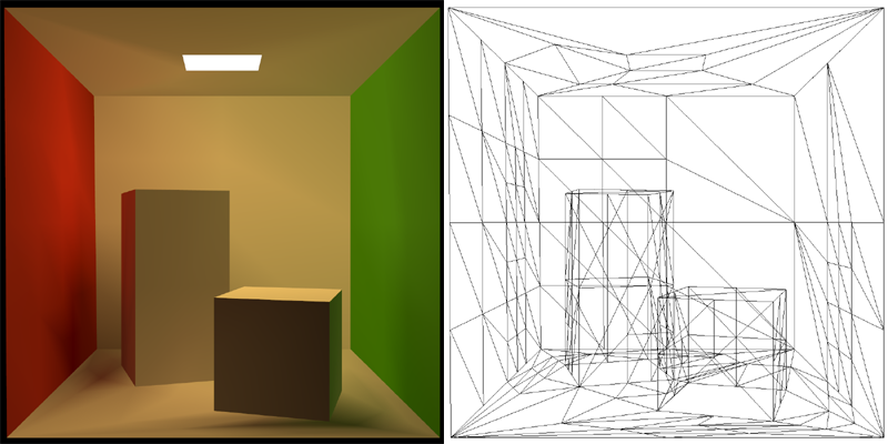
The full Cornell box. Artifacts around the
shadow discontinuities are caused by the uniform and low tessellation. 1548 triangular patches and
six iterations have been used in the simulation. See
here for the reference rendering from
Cornell University. This radiosity mesh with baked in illumination
is available for download.
|
|
|
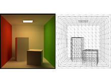
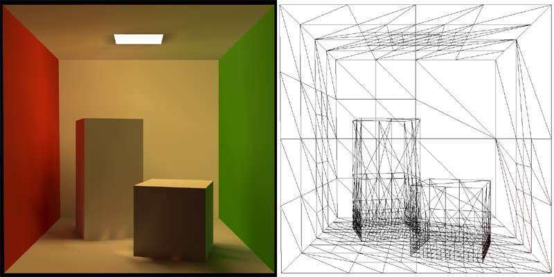
Radiosity solution computed on a mesh refined by using ID3DXPRTEngine:: ComputeDirectLightingSHAdaptive().
This tessellation did not do a good job at capturing potential discontinuities and appears rather random.
The base mesh used was the Cornell box with holes in ceiling and floor, aligning tightly with the light
source and the blocks.
|
|
|
|
|
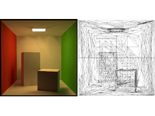
This mesh was computed by ID3DXPRTEngine::RobustMeshRefine(). The tessellator did a decent job
refining around the two blocks on the floor and nearby walls. The area below the blocks and behind
the light source is overly tessellated because the base mesh did not have holes for the light source
and blocks as in the image before.
|
|
|
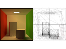
No more over tessellation with proper holes in the base mesh for the light source and the blocks.
Here RobustMeshRefine() fails to refine the mesh enough. The API does not provide a way to increase
the refinement any further. Calling it several times on the mesh did not yield good results.
|
|
|
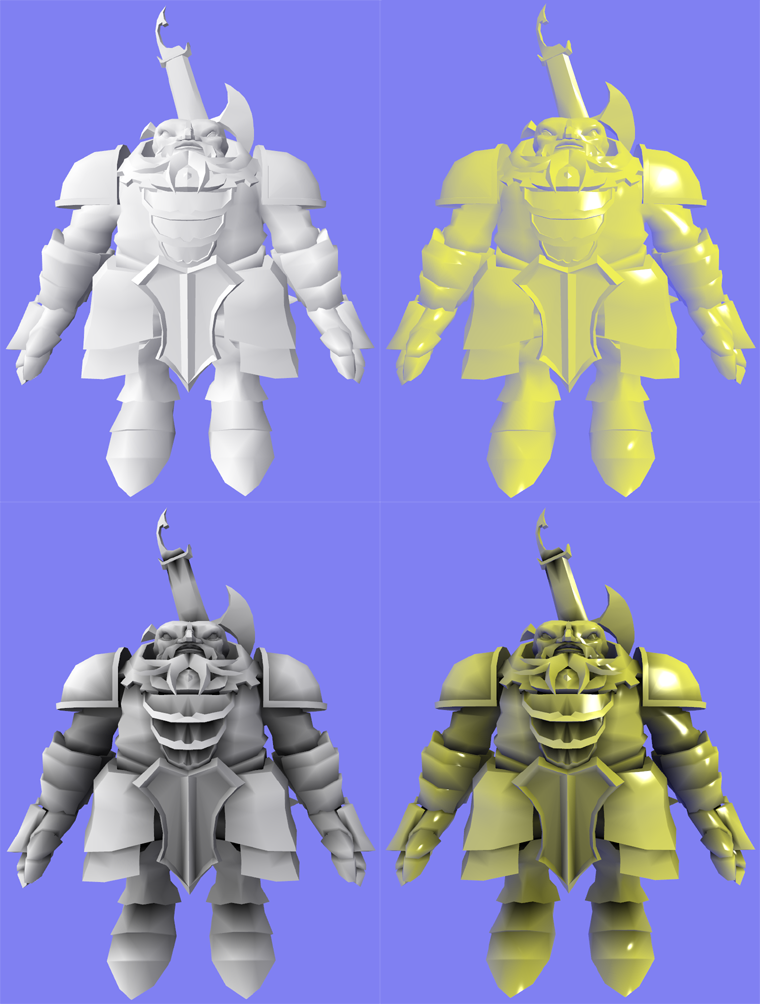
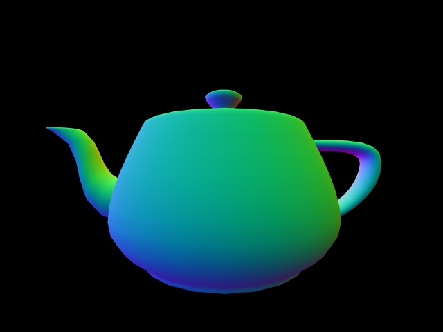
Ambient Occlusion
An ambient occlusion (AO) pre-processor I implemented. The accessibility of each mesh vertex is computed
as a pre-process. It is encoded by scaling the normal of each vertex. This removes all runtime
cost from AO because no extra storage or computation is required. It also enables renders which were
not written with AO in mind to render these pre-processed meshes.
|
|
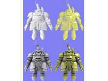
The 'Dwarf' mesh from the DirectX SDK rendered with a Gooch and a wrap lighting shader. The
lower images take the accessibility into account and have a more realistic look.
|
|
|
Another mesh with the same four shaders. Pre-computation time for the meshes shown here
is just a few seconds. Realtime display of the meshes is done using OpenGL and
GLSL. This mesh with baked ambient occlusion is available for
download.
|
|
|

|
|
The offline process for computing the ambient occlusion is implemented with the raytracer of my
physically based rendering experiment.
Sampling works by warping
Hammersley samples on a hemisphere and then rotating them into a basis formed by the normal of the
surface.
|
|
Spherical Harmonics
If you got no clue what this is about, there's an excellent introduction level article by Robin Green available
here. Also check the entries
on Mathworld and
Wikipedia for a more general and mathematical
description. Two of the
leading researchers in that subject, Ravi Ramamoorthi and
Peter-Pike Sloan have lots of more advanced material.
Precomputed Radiance Transfer (PRT), SH Irradiance and Relighting are a rather new topic in realtime
computer graphics, but there's already plenty of fascinating material out there. SH and
PRT are also features of the D3DX library in the DirectX SDK.
The program shown in the first picture is available for download.
|
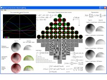
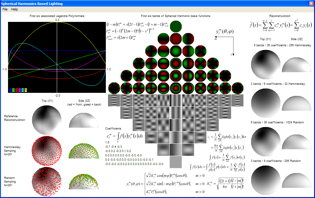
A test program I wrote which implements the entire sampling / coefficient extraction /
reconstruction pipeline. On that picture it only approximates a hemisphere lit by three
point lights and some SH basis function, but any sophisticated global illumination algorithm
could be plugged in.
|
|
|
|
|
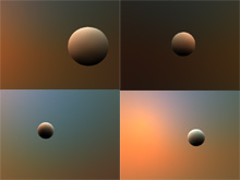
A sphere lit by an environment map using a 4 band (16 coefficients) SH approximation.
The physically based skylight model used to generate the environments was implemented
by my friend François (Main author of Toxic).
|
|
|
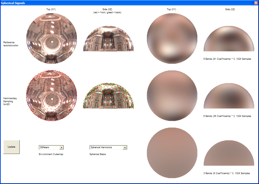
A test framework for comparing spherical basis functions. The functions being compressed
/ reconstructed are taken from cubemap images. The environment map used in the picture is
courtesy of Paul Debevec.
|
|
|

|
|
A more complex mesh lit by an dynamic skylight. Rendering is done with Direct3D and HLSL.
Mesh courtesy of Headus. Credits for exporting and
fixing it up go to my friend Carsten.
|
|
|
Work in progress of SH based soft shadows. The simple mesh is lit by a small disc-shaped area light.
Occlusion is stored as 64 coefficients (8 bands) quantized to 8 bit each. In the image various banding,
ringing and quantization artifacts are visible. Credits for the raytracer used to compute the occlusion
also go to François.
|
|
|
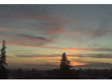
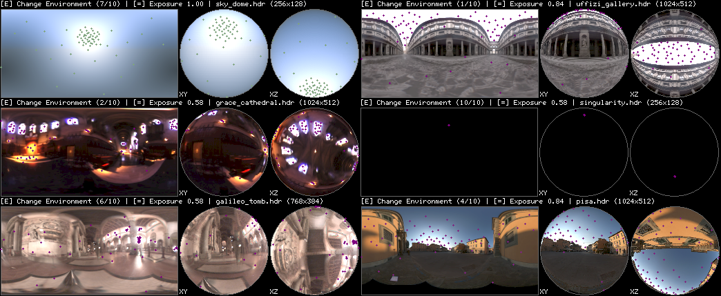
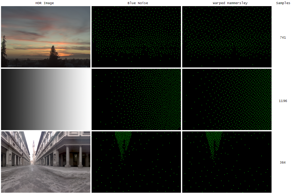
HDR Environment Map Sampling
|
|
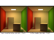
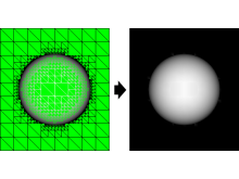
The algorithm nicely distributes the 64 samples over the bright parts of the image while preserving
their stratified / low discrepancy nature.
|
|
|
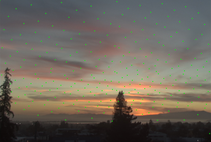
Notice how the typical Hammersley pattern is still visible after warping. 256 samples
have been used here.
|
|
|
|
|
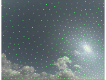
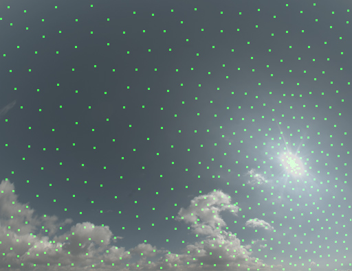
The samples here have been generated using the blue noise tiling. The bright sun
is correctly covered with dense samples.
|
|
|
A comparison between the sample distributions generated by warped Hammersley and
blue noise tiling.
|
|
|
Software Rasterizer
This is a simple triangle rasterizer with Gouraud shading, 16 bit depth buffering,
clipping and backface culling. All rasterization and interpolation is done in
fixed point. The idea behind this project was to provide a small and modular rasterizer
that can be used for various pre-process / offline rendering tasks that can't be performed
by a 3D accelerator. For example one might need floating point precision without relying
on a D3D9 class card being present. Another example would be a coverage buffer where every
pixel touched by a triangle needs to be filled, not just the ones that have their center covered.
The entire rasterizer is contained in a single 500 line header file and has no external
dependencies. Even though it wasn't intended for real-time rendering, it outputs a 2000
triangle model in 640x480 on a 1Ghz CPU at ~60FPS.

|
|
One of the advantages that this software rasterizer has over hardware accelerators
is the massive super-sampling. This picture has been rendered with 100 ordered
grid samples per-pixel.
|
|
Path Tracer
A path tracer implemented on top of code from my
physically based rendering experiment.
The renderer is using spectra instead
of normal RGB colors for greater realism. Algorithms are
kept unbiased and are implemented in a physically plausible way. The path tracer mainly serves
me as a test framework. Once a feature is working correctly it is ported back to the main
codebase of the physically based rendering framework. All of the renderings shown here are at
least partially based on the
Cornell box data and
measurements. The geometry, response / emission spectra and camera parameters have been
used. Differences between the images shown here and other renderings of the same data set
are the result of different tone mapping, spectral representation and output color space. Some
of the images also contain errors due to work-in-progress light transport algorithms. Excellent
references for more information about path tracing and realistic light transport in general are
the Physically Based Rendering book,
the thesis
of Eric Veach,
Henrik Wann Jensen's book
'Realistic Image Synthesis Using Photon Mapping' and the publications of
Alexander Keller.
|
|
A few early and simple renderings: lit (left), shadowed (center) and soft-shadowed (right).
The reconstruction filter for anti-aliasing is a Gaussian. Mitchell, Box and Triangle filters
are also supported. Tone mapping has been done using an integrated version of my
HDR Imaging tools. The ray acceleration structure used
is a 3D grid.
|
|
|
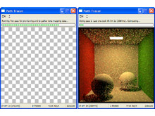
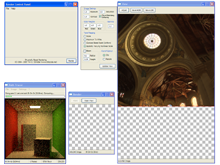
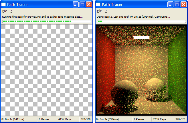
The GUI of the path tracer (done with Shiny). At startup a quick
low-quality pass is done over the scene to gather tone mapping data and to offer a first preview.
After that the unbiased renderer continues to add more passes. The variances reduces and the image
converges. An in-progress HDR image is optionally written after each pass.
|
|
|
|
|
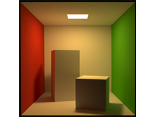
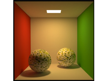
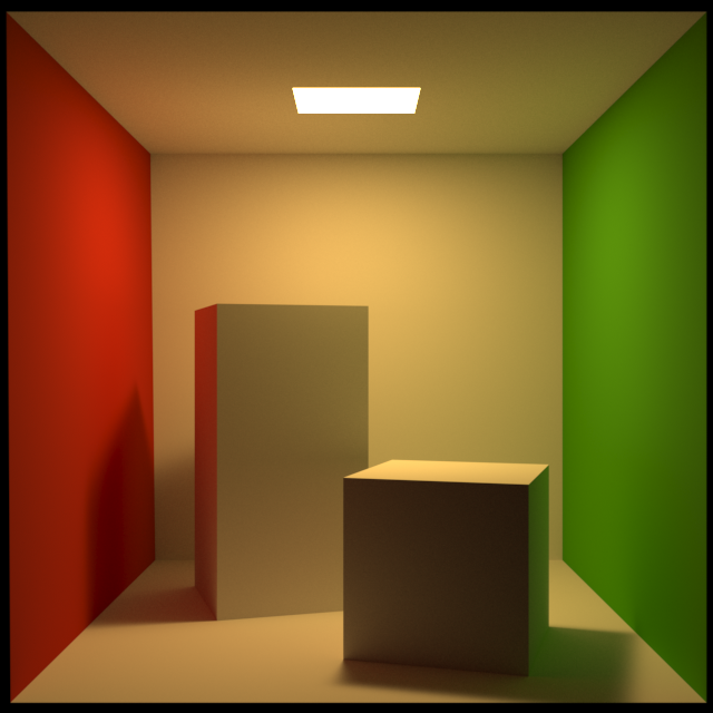
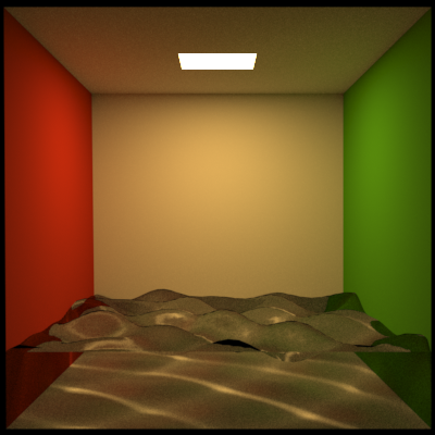
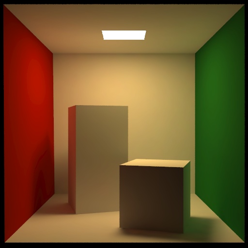
Rendering of the original Cornell box.
All reflectors are perfectly diffuse. Color bleeding from the walls can be seen. Compare to my
Radiosity renderings of the same dataset. The reference rendering
is available here.
|
|
|
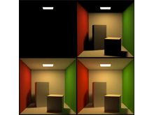
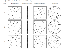
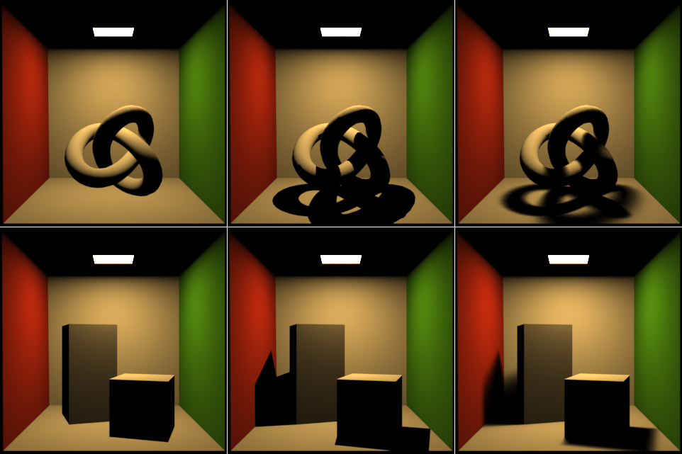
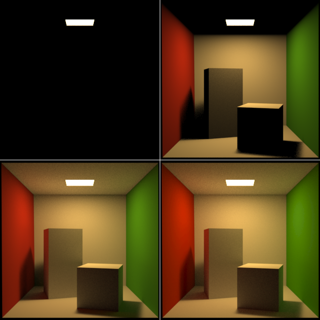
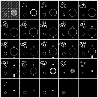
This image shows how the illumination changes when a limit for the maximum path depth is set. The
first image in the upper-left corner shows only emissive surfaces while the one in the lower-right
allows up to two bounces of indirect light. The actual renderer uses russian roulette to terminate
paths.
|
|
|
|
|
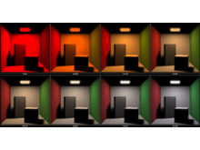
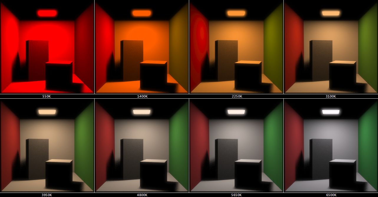
Here the light source has been replaced by a
black body radiator at temperatures ranging from 550K to 6500K. See
this
rendering from Maxwell Render for comparison. All images have
been toned mapped separately. It is hard to put them correctly into relation because of the very large
intensity range.
|
|
|
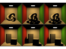
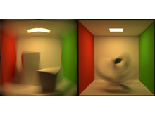
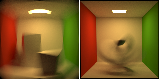
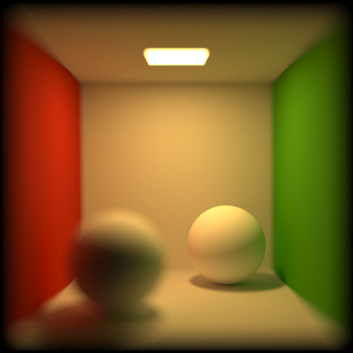
Fully raytraced motion blur. A spinning Cornell box (left) and a torus knot spinning inside a Cornell
box (right). It's expensive to compute motion blur this way but also simple and general. All features like
shadows and indirect lighting are taken into account. Here is an old
realtime OpenGL motion blur implementation I did.
|
|
|
|
|
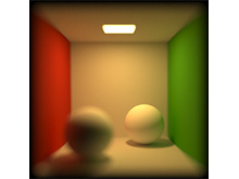
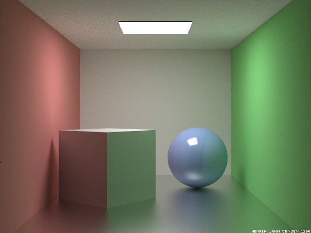
Camera depth of field effects. The plane of
focus is on the right background sphere, moving the left foreground sphere out of focus. This is actual 3D
DoF, similar to the motion blur before.
|
|
|
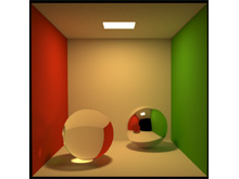
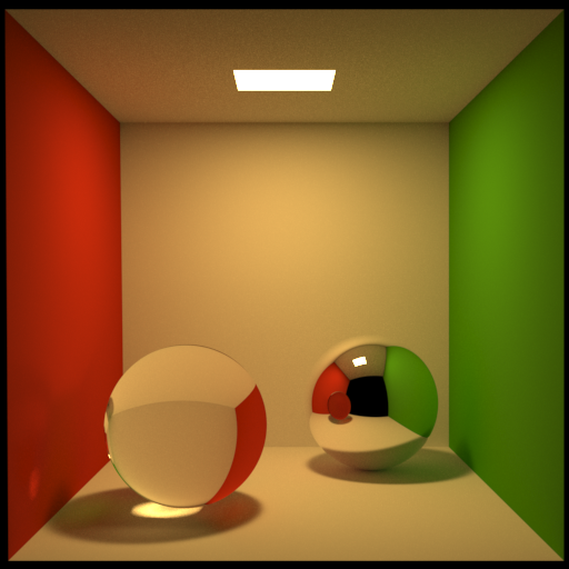
This image shows purely specular reflection and transmission. Caustics are visible below the left sphere
and on the red wall.
Here is a similar
image rendered by Henrik Wann Jensen.
|
|
|
|
|
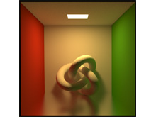
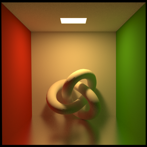
Cornell box with glossy floor. The reflection model used is the Blinn microfacet distribution.
The artifacts on the torus knot are due to the shading normal vs geometric normal mismatch.
Here is a similar
image rendered by Henrik Wann Jensen.
|
|
|
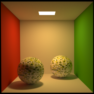
Two diffuse spheres inside a Cornell box which have their reflectance specified by a 2D texture.
The texture is a normal RGB image converted to spectral data at runtime. Lookups are done with
simple bilinear filtering.
|
|
|
|
|
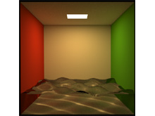
A water surface making nice caustics on the floor. Compare to
this similar image. The fact that the water is just a surface and not a volume makes this
scene invalid / non-physical. The water is also not using the dielectric Fresnel material but is
purely refractive.
|
|
|
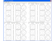
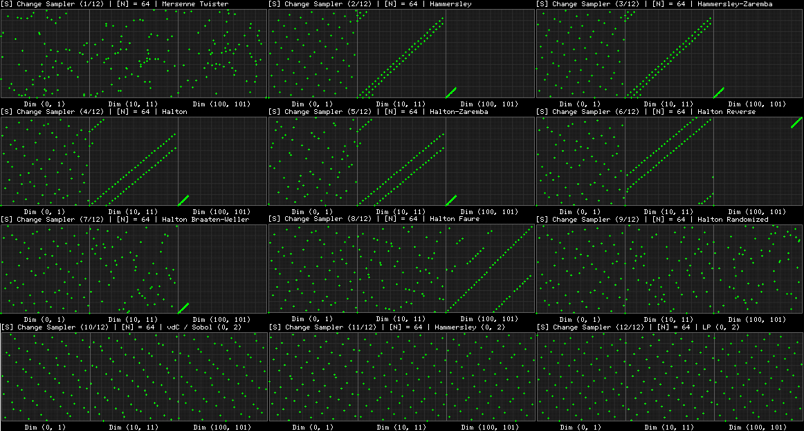
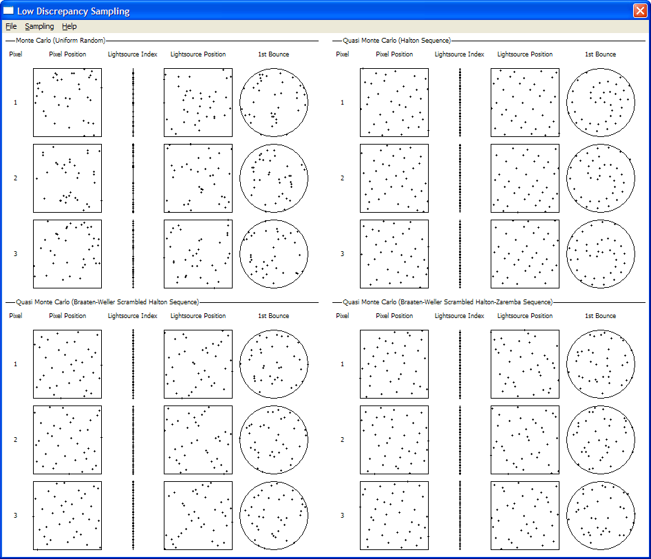
The test program. It is available for download.
It shows the distribution of several sequences for a typical multidimensional
integration problem in computer graphics.
|
|
|
|
|
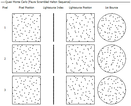
This image shows the first 64 samples of a Faure scrambled Halton sequence. See
Keller's
Monte Carlo And Beyond
slide 96 or 'Production Rendering' by Ian Stephenson (Ed.) page 225 for reference.
|
|
|
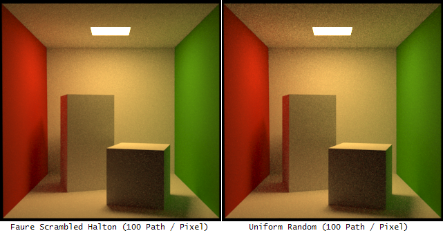
Two path traced images with 100 path per pixel. The left one uses a Halton
based QMC sampler while the right one uses uniform random sampling. Notice
how the QMC image has less noise, especially on the ceiling.
|
|
|
|
|
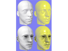
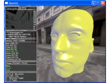
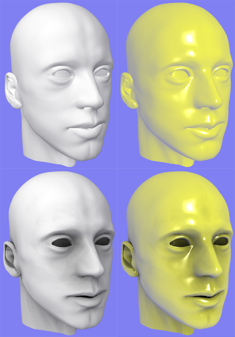
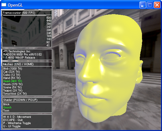
The test framework with an OpenGL port of my 3D UI Elements.
One can choose from various loaded meshes and shaders. The head in the picture is rendered with a
Gooch Shader from
3DLabs.
|
|
|
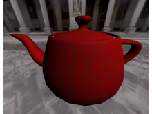
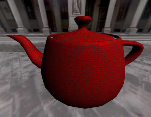
A simple brick shader, also from 3DLabs. I tried to get more fancy,
but at the time this program was written the GLSL support of nVidia and ATI was very early and complex
shaders often triggered software fallbacks or failed to compile.
|
|
|
|
|
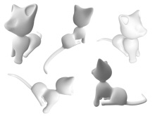
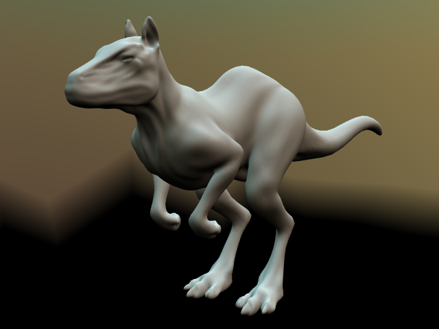
A 'Wrap Lighting' shader. Gives the model a nicely shaded appearance even from direction
where there is no light. Cat model done by my friend Wouter.
|
|
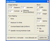
HDR Imaging
This is a tool I wrote to view and post-process high dynamic range (HDR) images such
as the ones produced by a physically correct rendering system or HDR photographs. The images
are loaded from Radiance image
files. Have a look here for some
HDR images from Paul Debevec. It
supports the tone mapping algorithms described in Matt Pharr's and Greg Humphreys' excellent
book Physically Based Rendering. Other features are
adding bloom, gamma correction, Floyd-Steinberg dithering and exposure / saturation /
contrast adjustment.
|
|
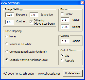
The GUI of the program. Hitting 'Update View' renders the image asynchronously
scanline-by-scanline with the new parameters. All Win32 and GUI code done with
Shiny.
|
|
|
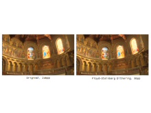
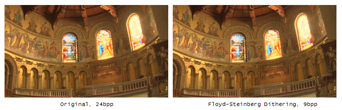
An example of the
Floyd-Steinberg Dithering. Normally used to dither down to
24bpp it is used here to create a 9bpp (3bpc, 8 shades) image.
|
|
|
|
|
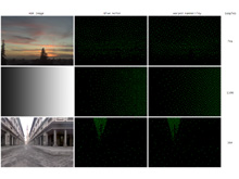
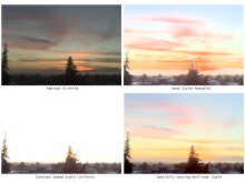
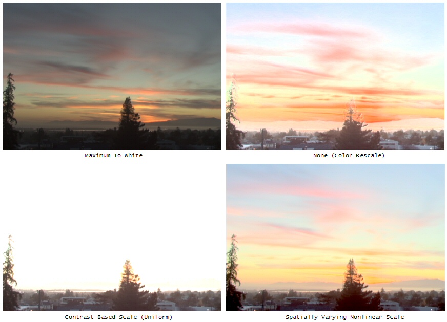
Comparison between different tone mapping algorithms. This is a difficult image because
of the extreme difference in luminance between the sky and the ground. The 'Spatially
Varying Nonlinear Scale' performs usually best, while sometimes on indoor images the
'Contrast Based Scale' looks better.
|
|
|
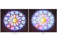
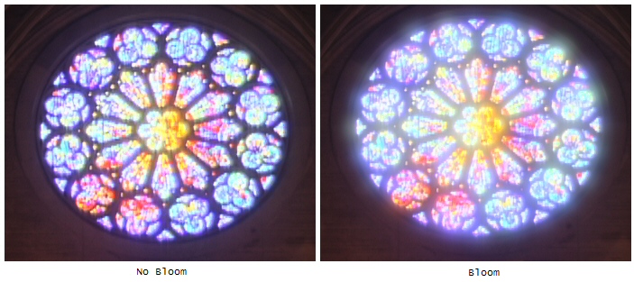
Bloom filter applied to a church window. It's somewhat slow to compute because of the
large filter width.
|
|
|
Physically Based Rendering
An early version of a physically based rendering system I'm working on. It's inspired by
Toxic and PBRT,
but doesn't reuse any of the actual code. The renderer is far from being ready, but
progressing slowly. So far some of the foundation code for spectral rendering,
sampling, filtering, HDR input / output,
BRDFs, cameras (DoF, motion blur etc.) and ray tracing has been written. An improved version of my HDR Imaging
tools are integrated. The GUI has been done with Shiny. I implemented
path tracing and radiosity using
the base code of this framework. Some of the images contain errors due to the work-in-progress
nature of the codebase.
|
|
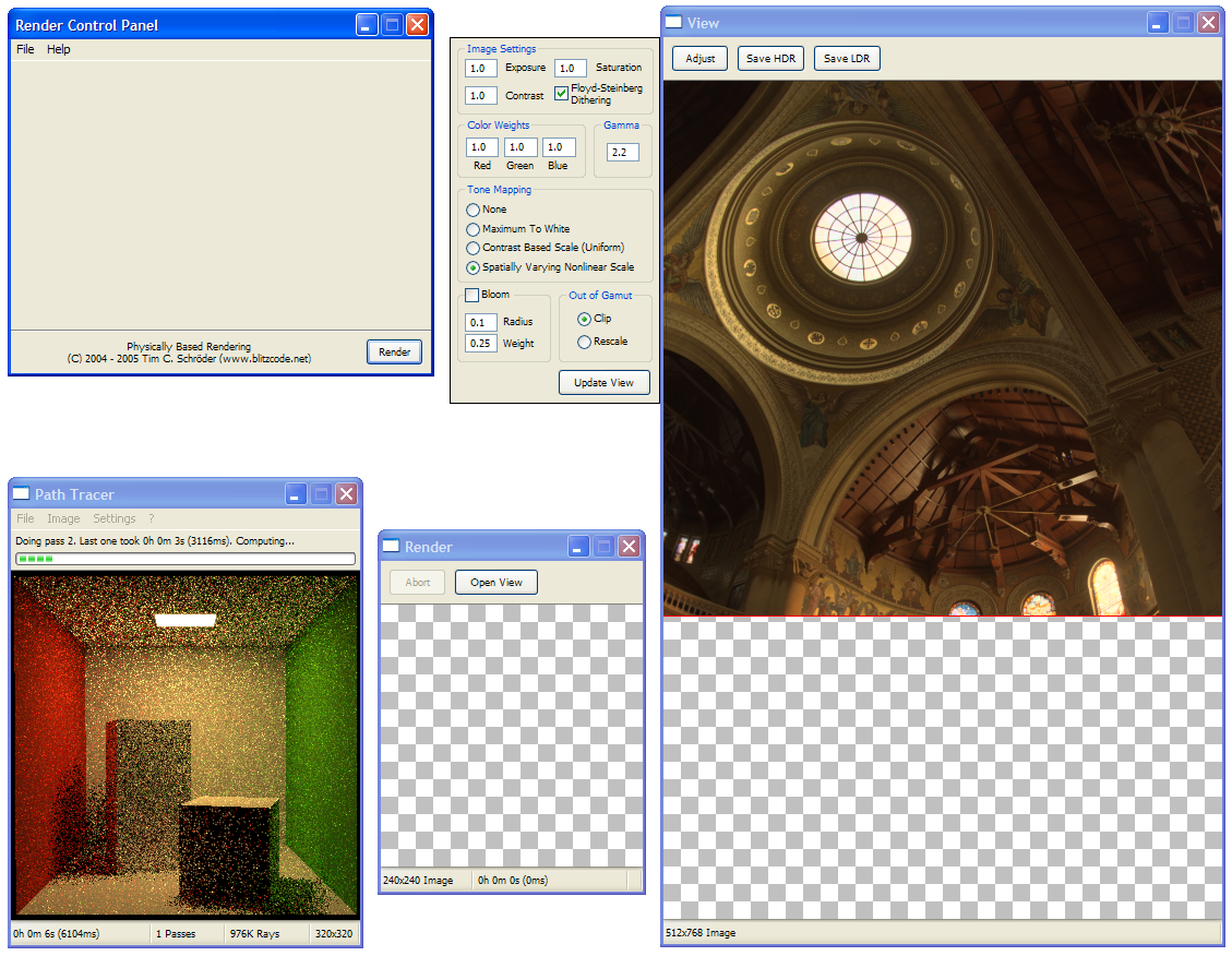
The test framework GUI for the renderer in an early state. On the right you can see the HDR
image post-process. It's hard to debug a GI renderer when you don't have proper tone mapping.
In the lower-left corner is a picture of a path tracer
which is based on this framework.
|
|
|
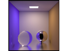
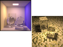
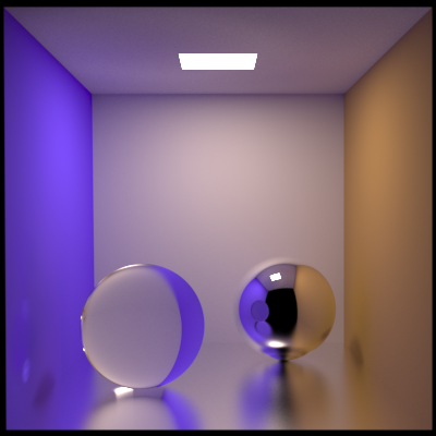
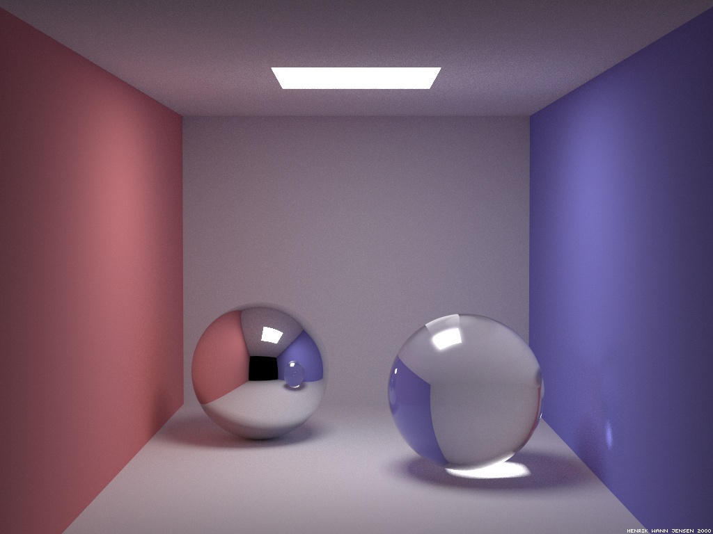
A Cornell box like environment with a
glossy floor and two perfectly specular transmissive / reflective spheres. Caustics can be seen
under the left sphere and on the blue wall. The light source is a black body radiator at a
temperature of 5000 Kelvin.
|
|
|
|
|
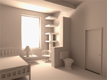
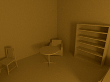
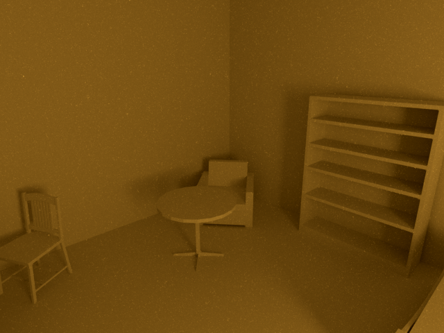
Rendering of a room scene taken from the WinOSI site.
This image had some additional post-processing from Photoshop. The scene was slow to render as it
contains a lot of indirect lighting.
|
|
|
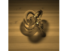
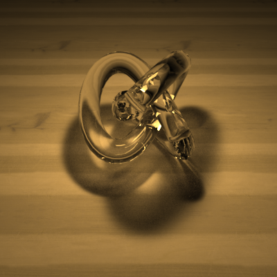
A torus knot made out of glass (index of refraction 1.5, dielectric Fresnel) casting shadows / caustics
on a plane. The reflectance of the plane is specified by a wood texture. The light source is a
square area light positioned above the torus knot. This image has been computed with over 26 billion
rays.
|
|
|
|
|
A rendering showing the part behind the camera of the room scene shown in an earlier picture.
The strong indirect lighting is causing lots of noise. Even after dozens of hours of rendering and
filtering the noise is still very visible. I plan to use better sampling, bi-directional
path tracing and adaptive filtering to improve this.
|
|
|
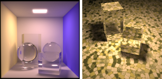
Two scenes containing objects made out of the same glass material as the torus
knot above.
|
|
|
|
|
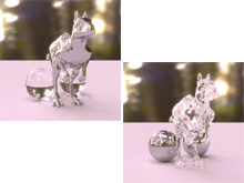
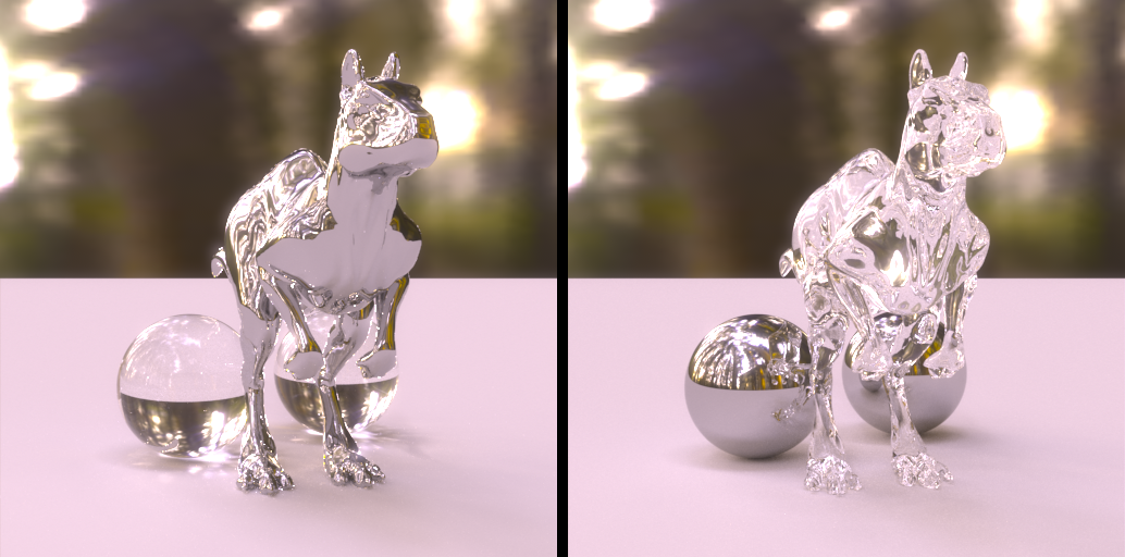
A complex mesh and two spheres on a plane illuminated by an HDR environment map.
In the left picture the sphere is a made out of glass and the 'Killeroo' mesh is
made out of steel. The right picture has the materials reversed. The left picture
had some Photoshop post-processing to remove noise.
|
|
|
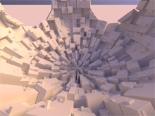
I got the idea for this scene after seeing these
renderings by Richard Rosenman. The geometry is generated
by the Greeble plugin and exported from MAX. All the light is
coming from the sky. I hacked up a little ad-hoc sky model based on my friend François' implementation
of the A Practical Analytic Model for Daylight
paper. This image has been computed with over 30K path/pixel.
|
|
|
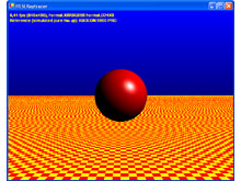
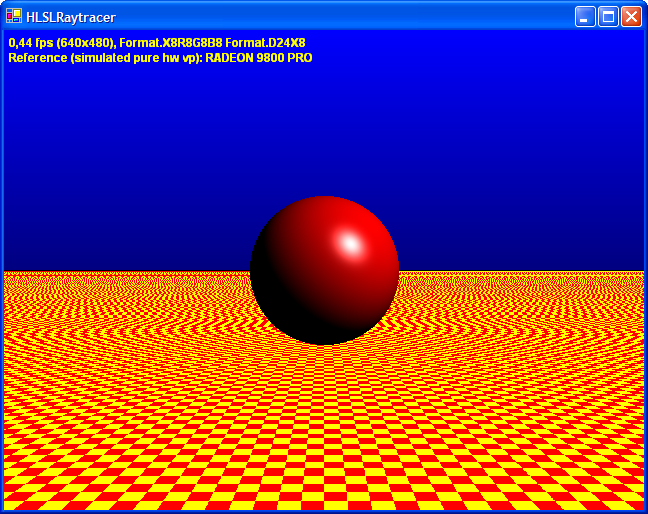
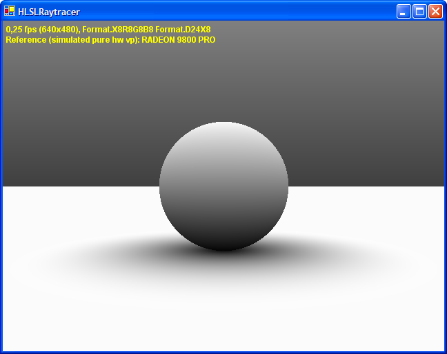
HLSL Raytracer
A simple GPU raytracer implemented fully in HLSL. The host application is written in C# and does little
more than drawing a quad covering the entire window. The managed / .NET version of the August 2005
DirectX SDK has been used for this little experiment. The Master's thesis of
Lars Ole Simonsen ('A Comparison of Acceleration
Structures for GPU Assisted Ray Tracing') has a more serious discussion of GPU based raytracing.
|
|
A checkerboard plane and a phong shaded sphere in front of a gradient background. This is running
on the reference rasterizer. 77 instruction slots are used by the ps_3_0 shader. It is hosted by a
DXUT based application.
|
|
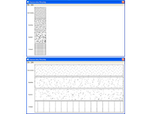
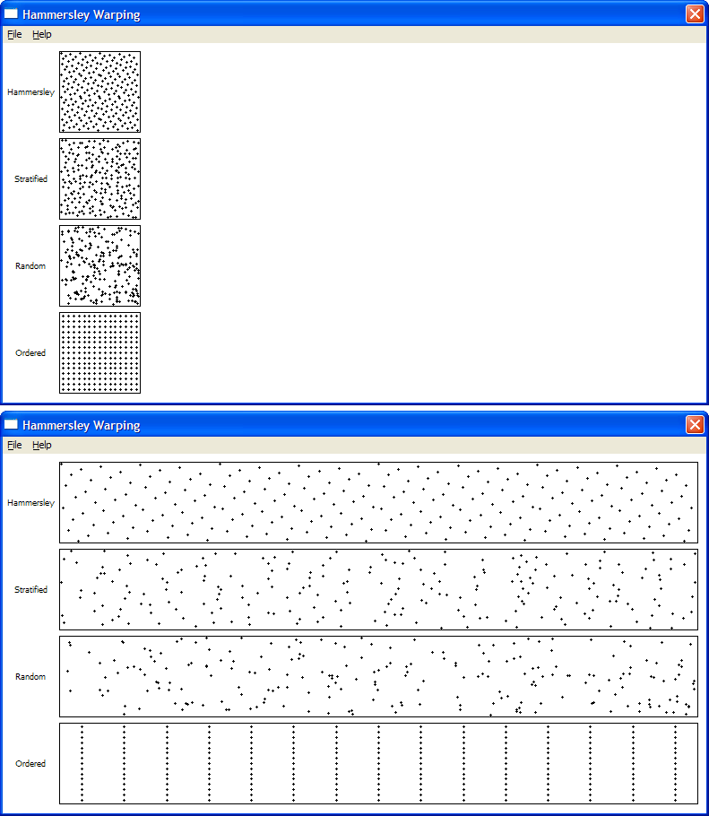
Sample Warping
A little program I wrote to demonstrate that the
Hammersley
low discrepancy QMC sequence stays well-distributed when being stretched / warped while
other sampling patterns like stratified sampling do not.
|
|
|
|
Photon Mapping
Photon mapping is a very powerful global illumination algorithm. It is implemented as a 2-pass algorithm
where the first pass traces and scatters photons from the lightsource through the scene and the second
pass estimates irradiance on the surfaces by computing local photon density and energy. My implementation
does a direct visualization of the photon map (no final gathering) and is strongly based on the explanations and sample code
presented by photon mapping inventor Henrik Wann Jensen in his book
'Realistic Image Synthesis Using Photon Mapping'. I highly recommend looking at it if you want to learn more
about photon mapping. Alternatively, see
this site for a well-done and brief explanation. This photon mapping implementation has been licenced
for commercial use.
|
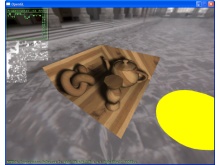
An architectural scene illuminated from the outside by a rectangular area light source.
This image has been computed with 1M photons from the light source plus ~800K reflected
ones. 500 photons are used in the radiance estimate.
|
|
|
|
|
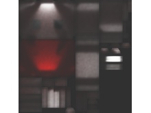
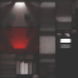
The 256x256 lightmap used in the scene above. It is mapped, packed and rasterized using
the same algorithm as my lightmap compiler.
This is the 24bpp lightmap after tone mapping, but the
HDR one can also be saved to quickly view the scenes with different settings. Notice the low
frequency noise in the illumination on the surfaces of the scene.
|
|
|
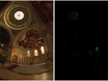
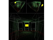
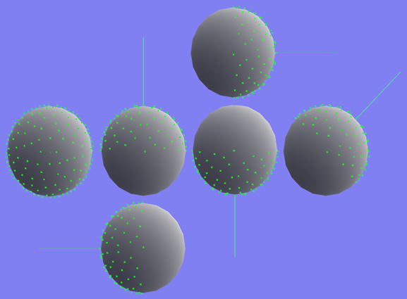
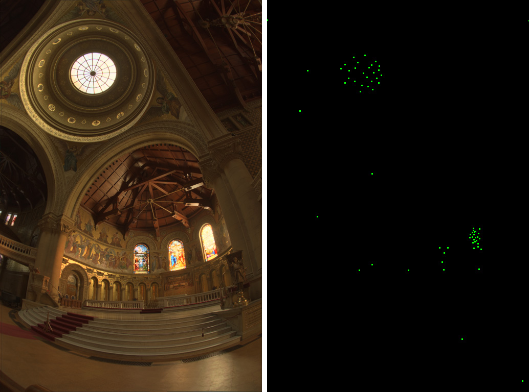
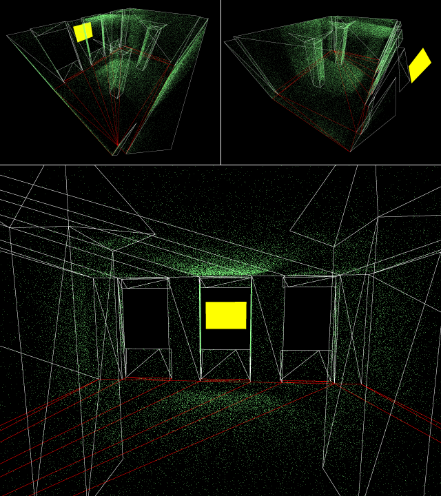
The photon map computed for the scene above. ~100K photons are displayed as green dots
on the surfaces of the model. The light source is yellow, the line colors indicate the
diffuse material color of the surfaces.
|
|
|
|
|
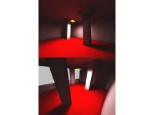
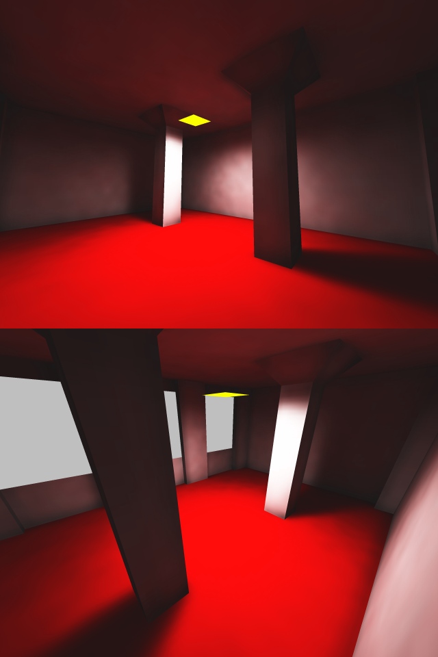
The red floor gives the walls a red tint by reflecting light from the small light source.
This effect is called 'color bleeding' and is an important part of radiosity simulation.
|
|
|
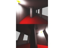
The small area light in the corner softly lits the room through indirect lighting.
The surfaces in the scene are all diffuse with a reflectivity of 50%, Russian Roulette
has been used for the photon scattering.
|
|
|
|
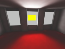
|
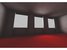
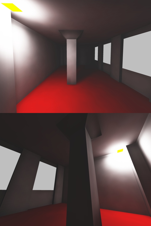
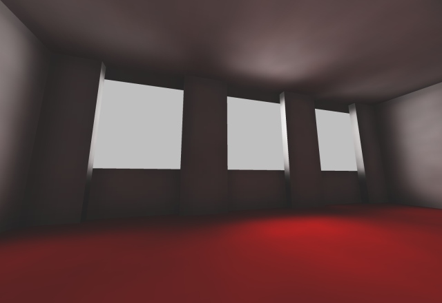
Smooth lighting across the entire room provided by a large area light source shining
through the windows (light source not shown). 2M photons were used in this scene.
|
|
|
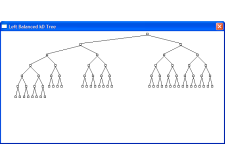
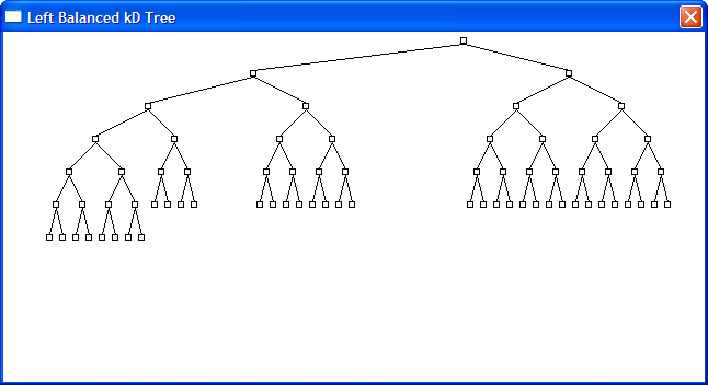
A program I wrote to develop the left balanced trees in my photon mapping implementation.
Such trees can be stored in a linear array - no need to explicitly
keep pointers to the child nodes. This feature
makes the representation extremely space efficient and well-suited to store kD Trees for Photon Maps.
This
paper has a nice explanation of the algorithm.
|
|
|
|
|
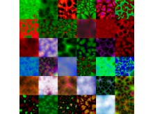
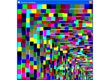
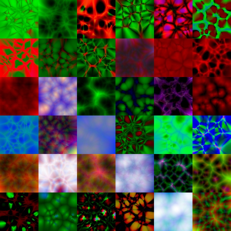
A small selection of the textures which the program randomly generates.
|
|
|
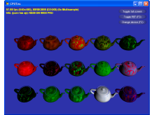
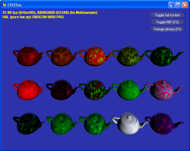
For another project of mine I wanted to know how fast I can transfer data from CPU to GPU.
This test program (Written with the DXUT framework from the October 2004 DirectX SDK) uploads
a bunch of procedural textures every frame and renders with them.
|
|
|
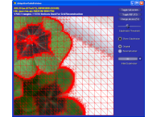
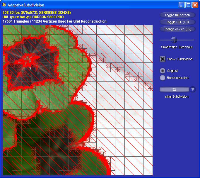
Adaptive RTRT
This is a test program for an adaptive realtime-raytracing (RTRT) algorithm. The image
plane is sampled at fixed gridpoints. If the color values between four adjacent grid points
diverge to much, the quad is split into 4 smaller ones. This is done recursively. The final
set of sparse sample points is uploaded to the GPU as a triangle mesh. In this way the
interpolation can be done on the GPU, where it's very cheap. Also further post process effects
such as glare and blur can be added. One problem with this approach is the upload time for the
huge triangle arrays generated. The impact of this can be reduced by having a tight encoding
scheme for colors and 2D positions of the grid vertices. Another issue are the T-junctions which
are introduced due to adjacent quads with different subdivision levels. This problem is not
easy to fix when realtime performance is desired. The current implementation is very optimized,
and will soon be driven by an actual ray tracer instead of the placeholder image / test ray tracer
seen in the screenshots. See
here for another RTRT using this approach.
|
|
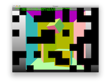
The test program. The nice GUI was done using the build-in facilities of the DXUT library
from the December 2004 DirectX SDK. For the test program a static image is sampled instead
of tracing rays.
|
|
|
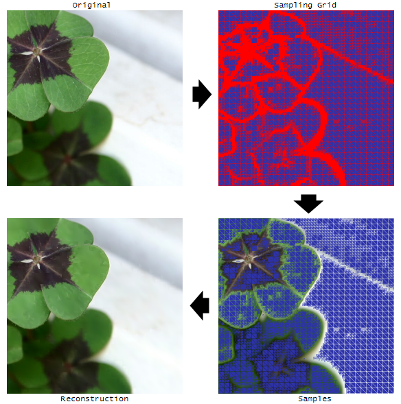
The basic algorithm. Note that step 2 and 3 are actually done interleaved because the
way the grid construction progresses depends on the values of the samples.
|
|
|
|
|
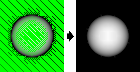
The subdivision code driven by a little test ray tracer. The sphere moves so I could
make sure there are no artifacts with the subdivision for moving objects.
|
|
C# Game Engine
This is a work-in-progress of a game engine written in C#. I started this project to
get more fluent with C# 2.0, .NET 2.0 and managed Direct3D. Another goal was to get
a nice framework for rendering and physics experiments. The engine can load Quake3 maps
and models to get some data for testing and experimenting. All data is directly extracted
from Quake3's PAK files. ZIP file handling is done with
SharpZipLib. So far loading of Q3 BSP Files
and MD3 Models
is supported. A fair amount of framework classes for things like accessing system timers
and smooth camera controls have been written. An XML based configuration system allows
tweaking engine parameters easily. The input system also uses XML files to bind keys to
actions. All rendering is done using managed Direct3D (April 2006 SDK) and the effect
file framework.
|
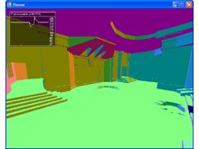
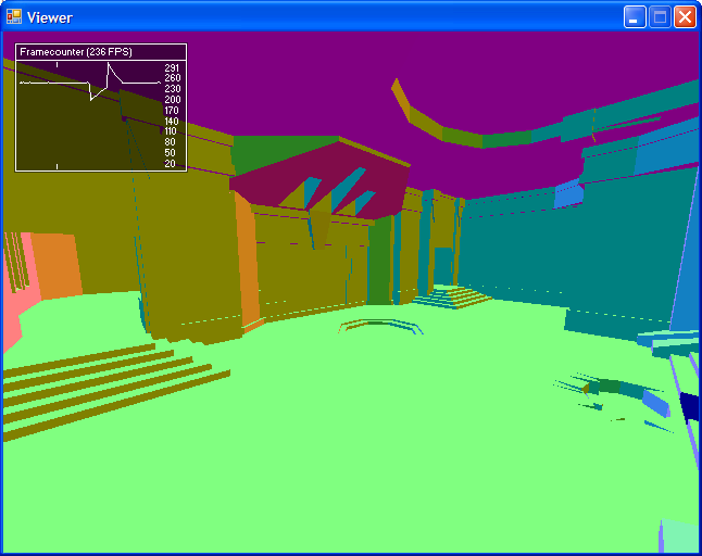
Screenshot of the Q3DM1 map. Rendering is still very basic and incomplete. A C# port
of my 3D UI Elements is shown.
|
|
|
|
|
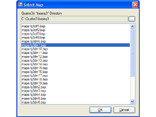
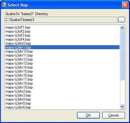
Simple WinForms 2.0 dialog for map selection. The list of maps is directly
extracted from the PAK file.
|
|
Lightmap Compiler
A lightmap compiler that does mapping, packing and lighting. It's basically
a Quake style lightmap generator. A triangle mesh is parameterized to a 2D
texture and illumination information for the surfaces is computed. The
parameterization is done by grouping triangles into clusters and projecting
them into a 2D coordinate system on the dominant plane of the cluster. To
improve the quality of the mapping, care is taken to align the coordinate
system to a boundary of the cluster. Then the individual clusters are packed
into a single texture using an kD tree based texture packing code. Once
everything is mapped and packed nicely, the rasterization starts. It's done by a
tweaked version of my software
rasterizer. The illumination model used is the diffuse component of Phong
shading plus a shadow term. The shadow computations approximate the occlusion of
a spherical area lightsource by sampling with a ray tracer. The ray tracing is
accelerated through a 3D grid accelerator. The compiler itself is a DLL with
a COM style C++ interface and has been licensed for commercial use.
|
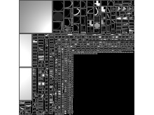
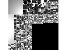
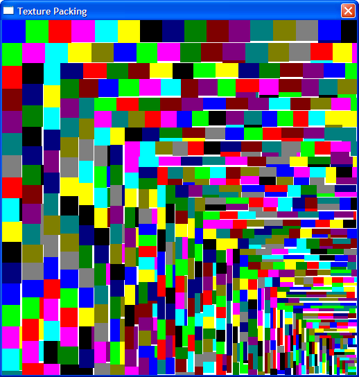
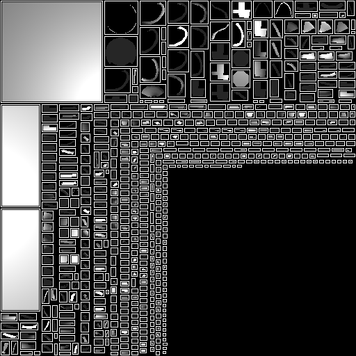
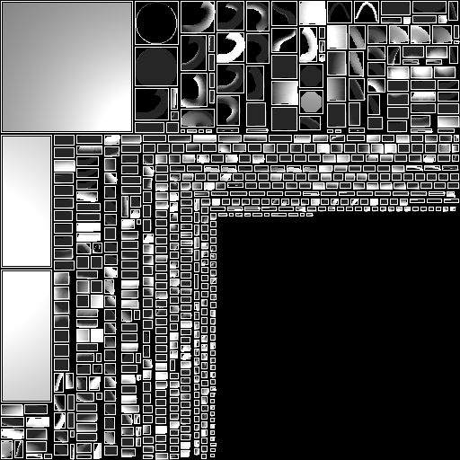
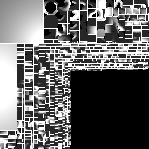
A test program for the texture packing algorithm used arrange the triangles in the
lightmap. The rectangles are grouped by size because the packing is more tight when the
big pieces go first. The white areas are unmapped and would be wasted. The packing
algorithm itself is using a kD tree and is pretty simple overall. Available for
Download.
|
|
|
|
|
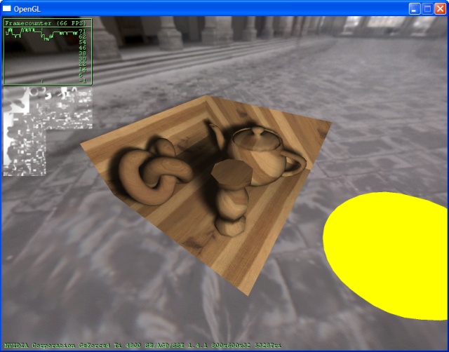
The OpenGL test framework showing a scene illuminated by an area light source.
The upper left corners shows a FPS display and the lightmap used for this scene.
Using a sufficiently high lightmap resolution and the mapping and rasterization
approach described below, this scene with many complex and smooth surfaces can be
mapped nearly completely free of seams.
|
|
|
|
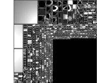
The initial lightmap for the scene above. Cluster AABBs are drawn as white rectangles.
Using this lightmap would result in seams and smoothing artifacts. The gaps between
the clusters are reserved for smoothing related lumels which are added in the next two steps
to fix these artifacts.
|
|
|
Here triangles adjacent to the cluster boundaries have been added. Note that they are
not actually mapped to the clusters - they are just replicated among adjacent clusters
to allow smooth interpolation across cluster boundaries. There is still a gap between
the clusters so border preserving filtering algorithms can recognize clusters.
|
|
|
|
|
As a final step the remaining gaps are filled with pixels taken from the nearest
cluster border. This removes all remaining artifacts caused by MSAA, MIP-Mapping
and bilinear filtering. Note that the actual lightmaps are processed with
a border preserving blur filter and have shadow information in them. This was
omitted for clarity in these three images.
|
|
|
The scene from my shadow volume and per-pixel attenuation demo
( Compare). Notice the depth
correct soft shadows and the smooth mapping.
|
|
|
C++11 Ray Tracing / Marching
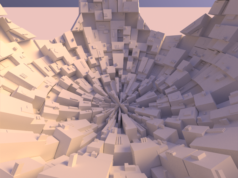
This is a basic C++11 OpenGL viewer application running a ray tracing /
marching kernel for each tile in a pool of worker threads. The purpose of
this application is to be a test framework for some rendering ideas I
plan to explore.
The source code for this project is
available on GitHub.
|
|
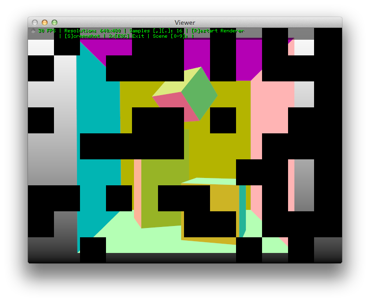
The GLUT / OpenGL viewing application with custom font rendering. The
image is being rendered in parallel tile-by-tile.
|
|
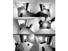
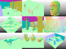
|
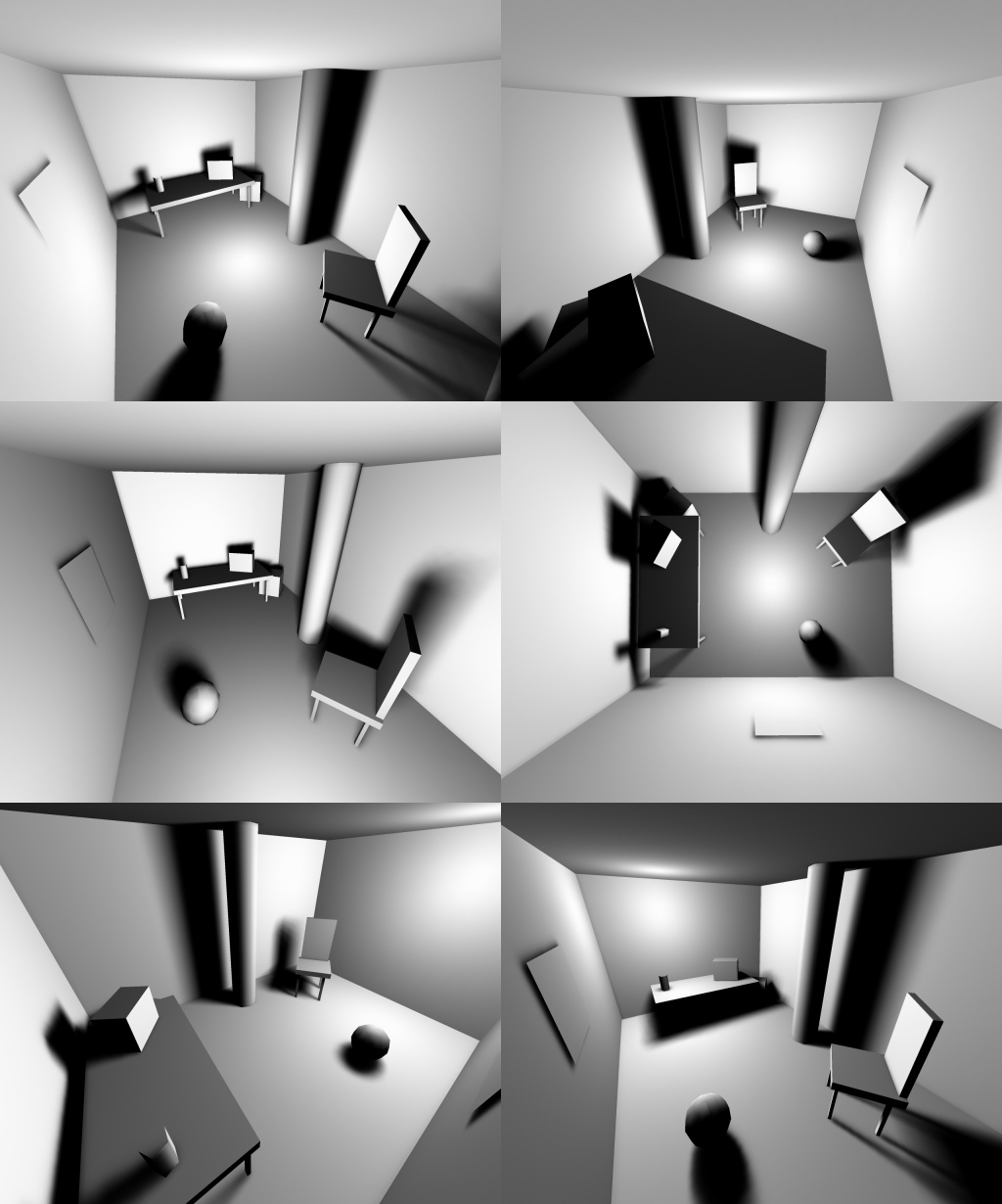
Some of the test scenes. Mostly used so far to debug intersection /
distance test errors, will be used for some lighting and shadow
experiments in the future.
|
|
|
|
|
| |


